
 EDGECAM 4 & 5 Axis Machining
Advanced CADCAM Software Solutions For The Manufacturing Industry
EDGECAM seamlessly integrates 4 and 5 axis simultaneous machining within its milling and mill/turn environment to allow a range of multiaxis cutting strategies to be applied to the most complex tooling or components.
EDGECAM offers a wide range of 4 and 5 axis strategies applicable to solid and surface geometry.
Features at a glance:
- Intuitive, easy-to-use graphical user interface.
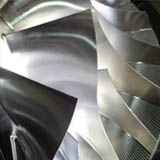
- Ideal for the rotary machining of automotive and aerospace components.
- Wide range of advanced options providing complete control of the tool.
- 5 axis modules include full machine simulation to aid visualization of the machining process.
EDGECAM has now made this easier to use with the operational style interface yet still have all the control required for the higher demands such as :
- SWARF cutting for machining of variable taper walls.
- 5 axis finishing across multiple surfaces with control over lead/lag and side tilt angles 5 axis profile machining for slotting, de-flashing and trimming of sheet forms.
- Full support for all common tool profiles, including lollipopcutters.
- Easy-to-use machining strategies are geared to maximize productivity and quality.
Introduction to 5 Axis is made easier with the 3 to 5 axis tool conversion and the peace of mind that the program is correct using the machine tool simulator.
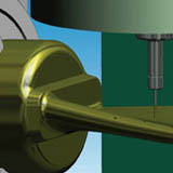
EDGECAM’s 4 axis strategies are ideal for the rotary machining of automotive and aerospace components such as camshafts, crankshafts and blades, as well as the production of rotary dies and components for the oil & gas industry.
4 and 5 axis simultaneous machining offer key advantages over conventional indexed 3-Axis machining:
- Reduced cycle time by machining complex components in a single setup. In addition, dimensional accuracy can be significantly improved through the elimination of positioning errors between setups.
- Improved surface finish and extended tool life are achieved by orienting the tool to maintain optimum tool to-part contact at all times.
- Improved access to undercuts and deep pockets - through tilting the tool or component allows shorter series tooling to be employed, eliminating the
need for secondary setups. - Reduced fixturing, as the cutter can be presented to the component at any
required angle.
5 axis machining is now common place in all areas of manufacturing as high technology machines have become more affordable along with design demands requiring more complicated tool paths.
3 to 5 axis Tool Path Conversion. Using the knowledge of 3 axis machining methods, the standard EDGECAM milling cycles and operations can be used on a component then apply the 5 axis tool path conversion. This produce 5 axis movement where required, ensure tool lengths are kept to a minimum and the cutting tool and holder tilted away from the component avoiding any collision. This methodology is an easy way to move into 5 axis programming technology.
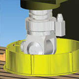
Turn Milling. Use the 4th axis rotary attachment on the milling machine to produce a turned shaft using milling cutters rather than using a lathe for a partial operation. This process relies on the percentage engagement of the milling cutter while rotating the component which is made simple using EDGECAM. The same principal is also used to produce cam forms. Five Axis Finishing Five axis finishing across multiple faces is similar to a parallel lace or scanning tool path but controls the tilt relative the surface which is driving the cycle.
SWARF Milling Side Wall Axial Relief Feed. This is common practice when driving the side of the tool along a surface which tilts from side to side, this is in common practice on many aerospace parts. The tilt is control by the surface wall and the tool lift controlled by the base surface or bounding curve.
5 axis Positioning. 5 axis machines are also capable of 5 axis positioning, also called 3+2. This is where the component can be positioned using a combination of 3 axis linear movement with 2 axis rotary movement. A standard 3 Axis machining method can then be applied on to the component face orientated towards the spindle. These tool paths may also have the 3 to 5 axis conversion applied.
Tool Path Control. 5 axis tool paths can result in large movements of the machine tool from what can be a very small cut on the component. These movements can cause severe damage the part and machine. EDGECAM provides methods for collision avoidance where the cutter and holder are checked for collision and the necessary tilts applied to move away from the potential collision area.Inverse Time Feed is control implemented to ensure the feed rate at the cutting tip is does not slow or dwell when small movements of the cutter produces a large movement of the machine tool. Inverse time feed allows a specified distance to move the tool during a specified time, this ensures the tool tip motion is correct and the machine tool movement will compensation to suit.

 Loading...


